

Automatic Power utilization using Microcontroller
- BY Balla Dani Hemanth
Automatic Room Lighting System is a microcontroller based project that automatically turn on or off the lights in a room. Electricity, being one of the most important resources, must be utilized carefully.
We often forget to switch off lights or fans when we leave a room. By using this system, we can intentionally forget about the lights as the system will automatically take care of them.
The digital World we are living in allows us to use different technologies to automatically perform certain tasks. Such automation is very useful in certain areas like energy consumption, reducing human efforts, improving standard of living etc.
The project implemented here is one such project where the microcontroller based system automatically controls the room lights.
The aim of this project is to automatically turn on or off the lights in a room by detecting the human movement. We implemented this project using 8051 Microcontroller and two Infrared (IR) sensors.
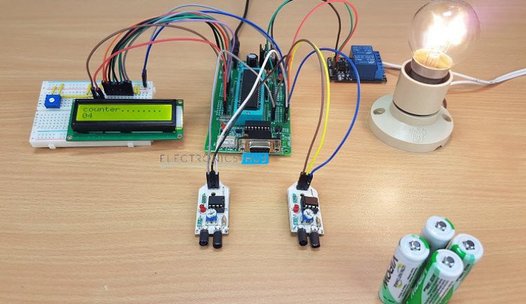
Since the job of the circuit is to turn on the light when someone enters the room and turn off the light when the last person leaves the room, the project has to internally count the number of visitors entering and leaving the room. Hence, the project acts as an Automatic Room Lighting System as well as Bidirectional Visitor Counter.
Warning: A 230V light bulb is used in this project and is connected to relay and mains supply. You should be very careful when connecting the mains wires.
Components Required
- AT89C51 Microcontroller (any 8051 architecture based microcontroller)
- 8051 Development Board
- 2 x Infrared Sensors
- 16 x 2 LCD Display
- 5V Relay Module
- Lamp
- Connecting Wires
- Power Supply
Circuit Description
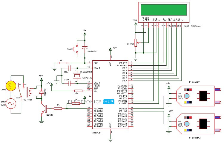
Let us see the design of the circuit for automatic room lighting project. The circuit diagram shows all the connections with respect to microcontroller. If you are doing this project on a development board, some of the connections mentioned in the circuit diagram might not be necessary.
Also, we have used modules for Relay and IR Sensor and hence, the connections are shown with respect to those modules only. Corresponding circuit diagrams are also provided.
Coming to the circuit design, a 16 x 2 LCD Display, two IR Sensors and a 5V Relay Module must be connected to the 8051 Microcontroller. First, connect the 8 data pins of the LCD to PORT1 pins i.e. P1.0 to P1.7.
The 3 control pins of LCD i.e. RS, RW and E are connected to P3.6, GND and P3.7 pins respectively. A 10 KΩ Potentiometer is connected to contrast adjust pin of LCD i.e. its pin 3.
Two Reflective type IR Sensors are connected to PORT2 pins i.e. P2.0 and P2.1. Detailed circuit of the IR Sensor is mentioned in the Component Description.
The input of the 5V Relay is connected to PORT0 pin P0.0. The detailed circuit of the 5V Relay module used in the project is explained in the component description section. Alternatively, you can construct the circuit as per the circuit diagram (which consists of 5V Relay, Transistor, Diode and a Resistor).
Component Description
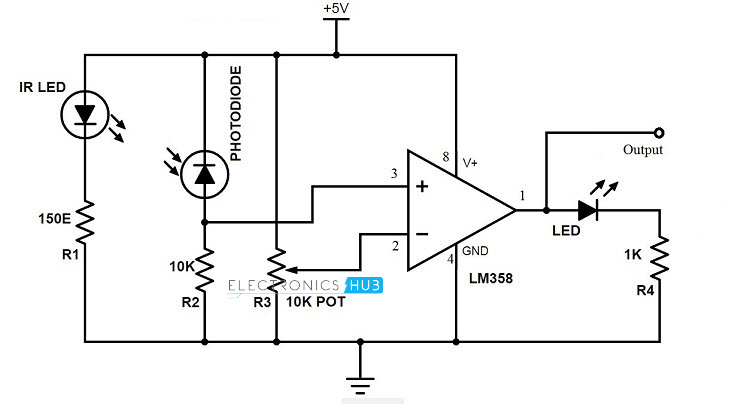
IR Sensor Module
An Infrared or IR Sensor is a simple circuit that is used to detect objects (Proximity Sensor) or measure distance (Range Finder). An IR Sensor consists of 3 components: an IR Transmitter (IR LED), an IR Receiver (like a Photo Diode) and a signal processing circuit.
We have used reflective type IR sensor modules in this project. The detailed circuit diagram of the module is shown in the following image.
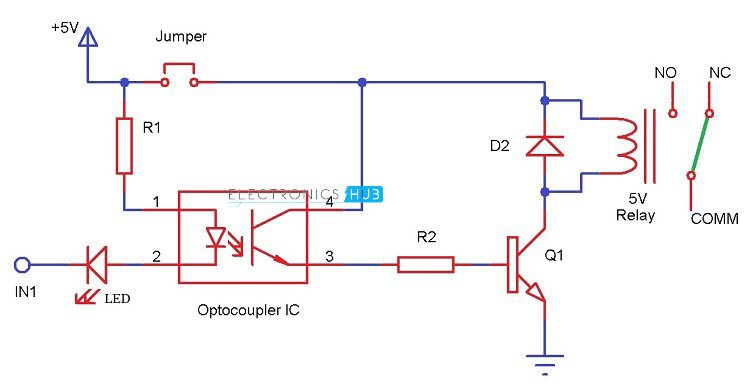
5V Relay Module
A 5V Relay Module is used in this project which helps 8051 Microcontroller to operate high voltage AC loads like a light. The detailed circuit of the Relay Module is shown in the following image. It consists of a 5V Electromechanical Relay, an Optocoupler IC, transistor, two resistors and two diodes.
 Working of the project
In this project, an automatic room lighting system is developed using 8051 microcontroller. The working of the project is explained here.
The main component of the project is IR Sensor and we have used two of them. The placement of the sensors is important as it will determine the functioning of the project.
Practically speaking, both the sensors must be placed on the either side of the door or entrance of the room. The sensor placed on the outside of the room is named as Sensor 1 and the sensor, which is placed on the inside is named Sensor 2.
When a person tries to enter the room, Sensor 1 detects the person first and then Sensor 2. This action will indicate the 8051 Microcontroller that the person is entering the room.
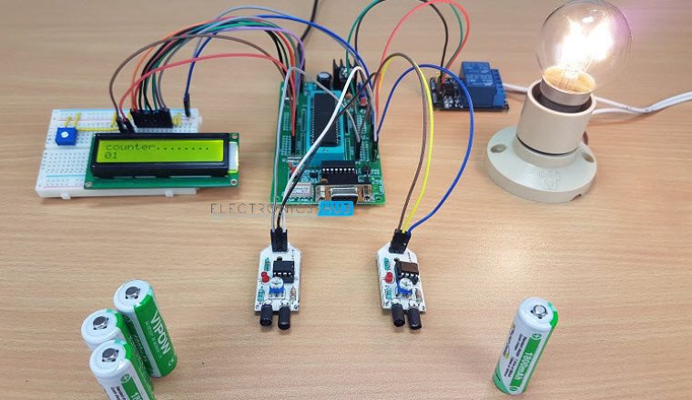
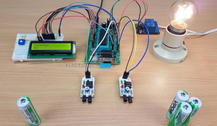
Hence, the microcontroller will turn on the light and also increments the visitor counter to 1. If there are more visitor, the microcontroller will keep the light turned on and increments the visitor counter accordingly.
When a person tries to leave the room, Sensor 2 detects the person first and then Sensor 1. This process will make the microcontroller to understand that a person is trying to leave the room and hence, it will decrement the count of visitors. The microcontroller will not turn off the light until the last person has left the room.
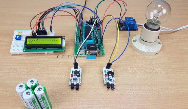
As the visitors start leaving the room, the visitor count will be decremented and when the last person leaves the room, the count be comes 0. During this point, the microcontroller understands that there is nobody in the room and turns OFF the light.
Caution: Be extremely cautious when using 230V mains supply.
Code
Applications
- Automatic Room Lighting with Bidirectional Visitor Counter can be used to automatically turn on the light in a room when a person enters the room and turn it off when the person leaves the room.
- The project can also be dubbed as a Bidirectional Visitor Counter it is an integral part of the Automatic Room Lighting circuit.
- The project can be modified with LEDs and as the number of persons in the room increases, the number of LEDs turning ON also increases.


0 Comments